Software Sessions
- May 2, 2019
- 30 min read
Today I began my first weekly software session, which gave me a light introduction to some of the programmes I will be learning to use over my three year course at University. Over the next three years throughout these weekly sessions I will be learning how to use programmes such as AutoCAD, Sketchup, Photoshop, and InDesign as these will become programmes that I will start to regularly use in my second and third year for my Interior Design projects. In this session, which has been my first of the year, I learnt some basic shortcuts to use when doing my work.
For example:
The snipping tool which is a screenshot utility. It can take screenshots of an open window, rectangular areas, a free-form area, or the entire screen. Snips can then be annotated using a mouse or a tablet, stored as an image file. To do this you click on the start button and search 'sn' and click enter to load up the snipping tool.
I have also learnt different shortcuts such as:
Copy= Ctrl C
Close down page= Ctrl W
Paste= Ctrl V
Undo= Ctrl X
Redo= Ctrl Y
New Page= Ctrl+Enter
Flicking through pages= Alt+Tab
Highlighting= Shift+Arrows
Copies what you just typed= F4
Finally, in this session I also learnt about different resolutions on different formats which will help me with my work to ensure that I use the correct resolution for pictures when presenting them in my work depending on the format I am showing them in. Resolution is affected by pixels and the amount of pixels per inch effects the picture quality and this is measured in DPI(dots per inch).
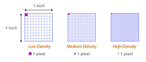
Some examples of different resolutions are:
Screen Resolution= 72 DPI
iPhone Resolution= 96 DPI
News Print Resolution= 150 DPI
Minimum Resolution= 225 DPI
Glossy Magazine Resolution= 300 DPI
Standard Photograph Resolution= 600 DPI
Good Quality Photograph Resolution= 1200 DPI
Sept 26, 2016
Over the last few weeks during my software sessions I learnt a variety of shortcuts in both AutoCAD and SketchUp. The shortcuts I have recently learnt have proven to be some of the valuable technical skills I have learnt, as now that I understand how to use these basic shortcuts I can combine these skills together to create detailed technical drawings; 3D models; renders and more.
These are the most recent AutoCAD shortcuts I have learnt:
1. The line tool (L)
2. The circle tool (C)
3. The array tool (AR)
4. The select tool (hold down cursor and drag either left-right or right-left)
5. The trim tool (TR)
6. The erase tool (E)
7. The arc tool (A)
8. The offset tool (O)
9. The OSNAP tool (OS)
10. The move tool (M)
11. The rotate tool (RO)
12. The copy tool (CO)
13. The fillet tool (F)
14. The pan tool (P)
15. The scale tool (SC)
16. Displaying the toolbar (TO)
17. The zoom tool (Z)
18. Creating layers (LA)
Through learning these basic AutoCAD skills one of my achievements was being able to combine these skills together to create piece by piece sections of my designs so that I could make 3D models of my designs by using my AutoCAD skills to create the different components and get them laser cut so that I can make my 3D models. From learning these skills I hope to be able to develop them further so that in the future I can achieved more complex and detailed drawings of my designs whether that be technical drawings e.g. plan views, elevations, front/back views etc. or being able to design more complex models or being able to create detailed cross sections. Throughout these first few weeks my biggest achievement that has come from these sessions was learning and understanding the initial basic processes of AutoCAD as it is a program I have never used before these software sessions, and in my opinion I have developed these skills well as I now feel comfortable using AutoCAD outside the sessions for my University projects and for independent learning and experimentation. However, their are still some aspects I need to improve. For example creating complex floor plans on AutoCAD is something I have experimented with but still find rather hard and this is a skill I would like to improve as it will become useful for my other projects in the future.
These are the most recent Sketchup shortcuts I have learnt:
1. Selecting a correct template for making models in SketchUp
2. The line tool (L)
3. The rectangle tool (R)
4. The orbit tool (O)
5. The push/pull tool (P)
6. The circle tool (C)
7. The arc tool (A)
8. The move tool (M)
9. The copy tool (M+Ctrl)
10. Making a group (triple click and then select 'Make Group')
11. Open the Large Tool Set (View>Tool Palettes)
12. The paint bucket tool (B)
Through learning these basic SketchUp skills one of my achievements was being able to combine these skills together to create more complex drawings e.g. a chess board and spiral staircase. I created these two objects as these allowed me to combine and experiment with the most Sketchup shortcuts/processes that I have learnt. Again one of my biggest achievements that has come from these sessions was learning and understanding the initial basic processes of SketchUp as it is a program I have never used before these software sessions. However, their are still some aspects I need to improve. For example I would like to improve my confidence when using SketchUp which will therefore improve my skills and will allow me to be able to use SketchUp independently. Hopefully, through independent practice of SketchUp I will become more confident with the program and the skills I have learnt, as well as experimenting with new shortcuts/process that I might learn along the way. From this independent study I hope to achieve enough of an understanding and enough skills to be able to create more complex and detailed 3D models of my designs.
Oct 24, 2016
A Shortcut Guide To AutoCAD
During my software session over the course of the last couple of months I have been learning how to use AutoCAD starting from the very basic process and shortcuts. Once I had learnt the basic processes and shortcuts of AutoCAD I then started to learn how to combine these processes together to be able to create more complex 2D drawings. Therefore, to show the processes and shortcuts I have learnt over the last couple of months in AutoCAD I will go through the processes I learnt during these weekly sessions as my personal guide to AutoCAD that demonstrates everything I have learnt so far in AutoCAD.
1. To draw a line in AutoCAD I use the shortcut which is to type the letter L and select the line option which creates straight line segments. By doing this I am able to create multiple lines that can be joined together. To create a line at a specific length I would type in the length of the line e.g. 250 and by pressing enter I would then get a line drawn at this specific length.


2. To draw a circle in AutoCAD I use the shortcut which is to type the letter C and select the circle option which creates a circle at an size. To create a circle with a specific radius I would again type in the radius I require e.g. 25 and by pressing enter I would then get a circle with a radius of 25.


3. The next process I learnt to use in AutoCAD was the array tool. This tool creates multiple copies of objects in a pattern. To use this tool I use the shortcut which is to type the letters AR and select the array option. To do this I started of by using the line tool to create a 500x500 square, to then create multiple copies I selected the whole shape, typed in AR and pressed enter so it would array my square. If you then want a specific amount of copies of the shape the settings of the array tool can be edited by changing the amount of rows and columns and the distance between the shapes both vertically and horizontally.


4. To select a whole shape, drawing, a series of shapes ect. without having the click on each individual line their are two different ways to do this. One of doing this is click left to right. By clicking on the left side of the shape you wish to select first you will get a random shaped blue like bubble over the shape as it follows the path of the cursor and then by clicking on the right hand side you will have then selected the shape. The other way to select something is to like right to left by doing you will get a green square over the shape and once you have clicked on the right hand side and dragged the square over the shape you wish to select and then clicked on the left hand side you will then of selected the shape.


5. To trim lines or shapes in AutoCAD I use the shortcut which is to type the letters TR and select the trim option which trims objects the meet the edge of other objects. To use this tool I started by using the circle tool to draw a circle and the line tool and drew lines going through the circle. Then by typing in the shortcut TR and selecting the trim tool, the next step is to then select the edge you want to trim up to, for this I selected the circle. Once I had done this I was then able to trim the lines intersecting the circle by clicking on the section of the line outside the circle so it would then trim the parts I had selected.


6. To erase lines or shapes in AutoCAD I use the shortcut which is to type the letter E and select the erase option which removes objects from a drawing. To use this tool I again stared with a circle that had line intersecting it. Then by typing the letter E and selecting the erase tool I can then select the lines or shapes I want to erase. The difference between this tool and the trim is that the trim tool will only delete the section of the line you have selected up to the point where it meets the original edge you selected, whereas the erase tool will just delete the whole line or shape.


7. To create an arc in AutoCAD I use the shortcut which is to type the letter A and select the arc option which creates an arc. To create the arc I selected the arc tool and the selected two different points which is where I want the arc to fit between. Once I had done this I was then able to drag to arc outwards to the size I wanted.


8. To offset lines or shapes in AutoCAD I use the shortcut which is to type the letter O and select the offset option which creates concentric circles, parallel lines and parallel curves. To use the offset tool I started off by using the line tool and drawing a line at a length of 500. Once I had drawn my line I then selected the line and typed in the letter O and selected the offset option. Next I typed in the distance I wanted between the lines which in this example was 50, and then by pressing enter another line will appear that is identical to the original line selected and is the specified distance apart. Then by clicking on the new line it will then automatically offset another line from that at the same distance or the distance may be changed by typing in a new number.


9. The next AutoCAD shortcut I used was the OSNAP tool and the shortcut for this is to type the letters OS which allowed me to set the running object snap modes. By opening the OSNAP tool I can change the setting in snap modes or turn snap mades on or off.


10. To move an object in AutoCAD I use the shortcut which is to type in the letter M and select the move option which moves objects in a specified direction a specified distance. To do this I started off by using the circle tool and drawing a circle with a radius of 25, once I had drawn the circle I then selected the shape and typed the letter M and selected the move option. After doing this I was able to then move the shape and place it another location. As shown in my print screen when moving a shape you are able to follow the mid point line so that the shape remains straight to where you originally placed your shape.


11. To rotate an object in AutoCAD I use the shortcut which is to type in the letters RO and select the rotate option which rotates objects around a base point. To do this I started by using the line tool to create a square and then selected the square and typed in the letters RO and selected the rotate option. Once I had done this I was then able to select a base point and rotate the object which will rotate around this base point.


To practice using the move and rotate tool further I downloaded a CAD document from the learning materials section on BlackBoard which was full of lots of different coloured squares. With the first group of squares I used the move tool to stack the boxes in lines and with another group of boxes I used the rotate tool to rotate the boxes so they were all straight.


12. To copy an object in AutoCAD I use the shortcut which is to type in the letters CO and select the copy option which copies objects a specified distance in a specified direction. Again to do this I started off by using the circle tool and drawing a circle with a radius of 25, once I had drawn the circle I then selected the shape and typed the letters CO and selected the copy option. After doing this I was then able to make exact copies of the object I had originally selected. Again as shown in my print screen when coping an object you are able to follow the mid point line so that the object remains straight to the original object.


13. To fillet an object in AutoCAD I used the shortcut which is to type in the letter F and select the fillet option which rounds and fillets the edges of objects. To do this I started by using the line tool to create a square and then selected the square and typed in the letter F and selected the fillet option. Once I had selected the fillet option I then typed the letter R, pressed enter, specified the fillet radius, pressed enter, I then selected the two lines I wanted to fillet together, pressed enter which would then create a curved joint between the two lines.


14. To pan in AutoCAD I used the shortcut which is to type in the letter P and select the pan option which adds a parameter with grips to a dynamic block definition. Doing this allowed me to be able to move across my drawing from one point to another.

15. To scale an object in AutoCAD I used to shortcut which is to type in the letters SC and select the scale option which enlarges or reduces selected objects, keeping the proportions of the object the same after scaling. To do this I started by drawing a 500x500 square using the line tool, then selecting the whole object, typing in the shortcut SC and selecting the scale option. I then dragged the object to scale I wanted.

16. To display the toolbar in AutoCAD I used the shortcut which is to type in the letters TO and select the toolbar option which allowed me to display, hide, and customise toolbars.

17. To zoom in AutoCAD I use the shortcut which is to type in the letter Z and select the zoom option which increases or decreases the magnification of the view in the current viewport.

18. To be able to see the layers in an AutoCAD drawing I used the shortcut which is to type in the letters LA and select the layers option which allows you to associates objects by their function or location; display or hide all related objects in a single operation; and enforce line type, colour, and other property standards for each layer. I did this by using the same boxes I used to practice the move and rotate tool and split them into layers and these are identifiable by colour.

Finally, to use a variety of these skills/shortcuts together I went on to learning materials on BlackBoard a downloaded a document showing the simple steps on how to create a chair in AutoCAD including the lengths of line and angles and from this I had to figure out which processes were used to create the chair. The shortcuts I used to create this chair were the line tool, circle tool, trim tool, erase tool, fillet tool ect.


Dec 19, 2016
A Shortcut Guide To SketchUp
During the last few months I have also been learning and experimenting with SketchUp, as well as AutoCAD, and I have been learning how to use SketchUp starting with the very basic skills and processes. Once I had learnt the basic skills and processes of SketchUp I then began combining these skills together to be able to create more complex 3D designs. Therefore, to show the processes and skills I have learnt over the months in SketchUp I will go through the processes I learnt session by session in order as my personal guide to SketchUp that demonstrates everything I have learnt in my software sessions regarding SketchUp. In my first SketchUp session I learnt that the first step for using SketchUp is to make sure I had selected the correct template. Every model in SketchUp is based on a template, which has predefined settings for your model's background and units of measurements. Here's a step by step guide on how to select a template in the 'Welcome to SketchUp' dialog box:
1. At the top of the dialog box, the Default Template field tells you the name of the currently selected template. To change the template, click the Choose Template Button or click the arrow next to the Template tab. The Templates tab opens with a list of templates that come with SketchUp.
2. Scroll through the list and select your desired template e.g. Feet, Inches, Millimetre's.
3. Click the Start using SketchUp button, and SketchUp opens, ready for you to start 3D modelling.

When using SketchUp I have always chose the millimetre's template for my 3D SketchUp drawings.
Some of the shortcuts I learnt during my SketchUp sessions are as follows:
Select- to use the Select tool you press the Spacebar.
Paint Bucket- to use the Paint Bucket you press the letter B.
Rectangle- to use the Rectangle tool you press the letter R.
Circle- to use the Circle tool you press the letter C.
Move- to use the Move tool you press the letter M.
Rotate- to use the Rotate tool you press the letter Q.
Tape Measure- to use the Tape Measure tool you press the letter T.
Orbit- to use the Orbit tool you press the letter O.
Zoom- to use the Zoom tool you press the letter Z.
Eraser- to use the Eraser you press the letter E.
Line- to use the Line tool you press the letter L.
Arc- to use the Arc tool you press the letter A.
Push/Pull- to use the Push/Pull tool you press the letter P.
Offset- to use the Offset tool you press the letter O.
1. One of the first shortcuts I learnt how to use in SketchUp was the line tool. The shortcut for this tool is to type in the letter L which then allows you to be able to draw a line down either the blue, green, or red axis. By using this shortcut, multiple lines that are connected can be drawn to create different shapes, in the example below I started by drawing a simple rectangle. The next shortcut I then learnt was the rectangle tool. The shortcut for this tool is to type in the letter R which then allows you to draw any size rectangle on either the blue, green, or red axis.

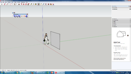
2. The next shortcut I learnt how to use in SketchUp was the orbit tool. The shortcut for this tool is to type in the letter O and then click and keep hold of the 'Scroll Wheel' on the mouse which allows you to move/orbit around the drawing/s you have created in SketchUp. This allows you to be able to view the drawings from all angles.
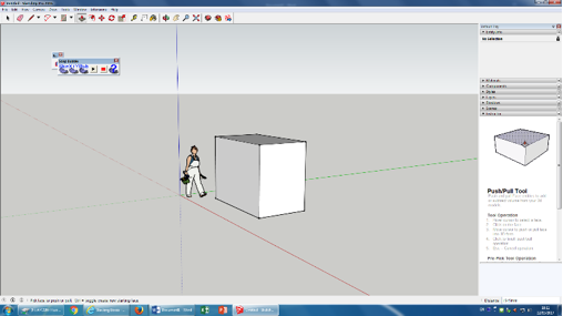
3. The next shortcut I learnt how to use in SketchUp was the push/pull tool. The shortcut for this tool is to type in the letter P. Once the push/pull tool has been selected you then click on the object you have drawn that you wish to use the push/pull tool on. This allows you to make object thicker or thinner.
To practice using the line and push/pull tool further I made a series of other shapes to create a house like structure; including doors and windows. To do this I used the line tool to draw different shapes e.g. a triangle for the roof, rectangles for the door/walkway and window; and then used the push/pull tool to either push/pull these shapes.

4. The next shortcut I learnt how to use in SketchUp was the circle tool. The shortcut for this tool is to type in the letter C. Once you have selected this tool you can then draw any size circle by simple just selecting a point and then dragging the cursor outwards until you get the size circle wanted.

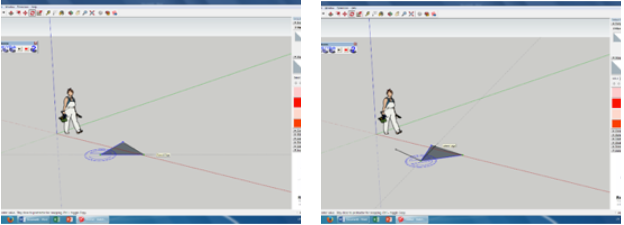
5. The next shortcut I learnt how to use in SketchUp was the arc tool. The shortcut for this tool is to type in the letter A. Once you have then selected this tool you then select two points that the arc all appear between and then you drag the cursor in the direction you want the curve of the arc to be, and then drag out the cursor as little or as much as you want to make the curve as prominent.

6. The next shortcut I learnt how to use in SketchUp was the move tool. The shortcut for this tool is to type in the letter M. To do this you must first select the object you wish to move. Once you have selected the object you then type in the letter M to select the move tool, then click the item you want to move, then move your cursor to move the selected object and finally click the destination point you wish to move the object to, to finish the move.
7. The next shortcut I learnt how to use in SketchUp was the copy tool. The shortcut for this tool is to select the object you wish to copy, then select the move tool by typing the letter M and then press and release the Ctrl button which then allows you to copy the object selected.

8. The next shortcut I learnt how to use in SketchUp was to be able to make separate, touching objects a group. To do this you have to triple click the objects you wish to make a group which will then select all the objects. After this you then right click and select the option that says 'Make Group'. Doing this then allows you to then click into the whole object and either edit just one component or allows you to make the same change to every object at once.

9. The next shortcut I learnt how to use in SketchUp was to be able to open the Large Tool Set which allows you to use more advanced tools within SketchUp. In SketchUp you can customise what tools are seen by showing or hiding tool palettes. To see a palette, you select View>Tool Palettes and then select your desired tool palette from the submenu that appears and one of the options that appears is the Large Tool Set.

10. The next shortcut I learnt how to use in SketchUp was the paint bucket. The shortcut for this tool is to type in the letter B. To do this you click the object you wish to paint and then by typing in B, select the paint bucket tool. Once you have selected the paint bucket tool I bar appears on the right hand side of the screen with various options such as: Solid Colours, Materials etc. By selecting the materials options you are then presented with various other options such as: Bricks, Roofing, Windows etc. By using these different options I was able to was the paint bucket to make the structure more like a house.

11. The next shortcut I learnt how to use in SketchUp was the rotate tool. The shortcut for this tool is to type in the letter Q. To do this you select the rotate tool, then a 360 degrees compass will appear. Place the compass on one of the edges of the shape you want to rotate, this will then become the point the shape rotates around. After this you then select another edge and then you can rotate your shape.
After learning how to use a variety of these tools I then combined their uses to develop my skills further and created a chess board. To create this I used a variety of tools such as: line, copy, move, arc, circle, group, and push/pull. By combining a few of these simple skills and shortcuts together I was able to make a simplistic chess piece and then a complete chess board.

Finally, to develop these skills further and to keep practising them, including the paint bucket tool I also created a glass spiral staircase.

Dec 22, 2016
During the first few sessions back with Paul I did a quick overview and recap on what I had learnt in first year by going over processes and skills that I had learnt throughout first year in AutoCAD, SketchUp and Photoshop. Going over some of these process, particularly in Photoshop and SketchUp was particularly helpful as over the summer I had forgotten how to do certain things within these two programs. Going over these processes again and how to use them and what they can be used for was also in preparation for my first module of the year which is going to be Architectural Technology and Spatial Design and for that project I am going to have to build SketchUp models and floor plans, elevations and cross sections in AutoCAD.
Oct 4th, 2017
In this weeks software session we learnt how to create a drawing boarder in AutoCAD. The reason for doing this was because for my current module that I am working on I have to create a set of floor plans, elevations and cross sections and my lecturer wants these to be set out in a professional manner which requires making a drawing boarder for my plans. In my drawing boarder/title block I included a revisions table, title, the designers initial which were my own, the date, the scale of the drawing, a disclaimer, my logo, the company logo of who I was designing for, the drawing number, my company address or site address and issue code.
To do this I first loaded the preset drawing boarder templates in AutoCAD by opening up AutoCAD, clicking the button that says 'start drawing' and either selecting 'Architectural Metric' or 'Manufacturing Metric'. However, when I had opened up both of these preset title blocks I didn't like the general layout of them so I decided to make my own from scratch which was fairly easy to do as I just simple had to put in lines and text boxes where I wanted them to create my boarder and make sure the lines of the text boxes were set so that they were coloured, therefore being visible.
To apply text to a drawing boarder/title block, I just had to double click anywhere on the drawing and then an information box appears. I then expanded the box and then filled in the information that I wanted the box to say, press 'apply' and then 'ok'. To insert a logo or image I had to save the image as a JPEG and then go to 'insert' and then 'attach', then I go through my files on my computer, find the image I want to attach and drop the image into place.
The title block I created was for my current module Architectural Technology and Spatial Design to give my final floor plans, elevations and cross sections a more professional finish. However, as I am happy with the look and layout of my title block I will continue to use this one in future modules if it is required.

Oct 18th, 2017
In this weeks software session I spent my time going over some different process in AutoCAD that I haven't really used until now but will come in handy for creating complex and professional looking floor plans, elevations and cross sections, as well as process that will help with putting the final touches onto a set of plans.
Firstly I looked at line weights and layers for line work. Both of these process are important to remember and use when creating a drawing a AutoCAD as line weights can help indicate the thickness of different sections of your drawing, as well as indicate what each line as, for example if its a structural wall or a internal wall and it can also be used as an indicator for materials. Using layers for different sections or different line weights or different materials is also helpful as not only can you switch between layers making it easy to work on different sections, each layer can be coloured differently making it easier to identify each section. Using layers also means that if I was to make a mistake instead of having to go back and lose half of my work I can focus on the section the mistake was made in, saving me time and making so that I don't have to lose loads of me work and then rebuild it all.


Then I looked into how to apply dimensions to a drawing in AutoCAD once I had the drawing in the space with the title block. When selecting how to display the dimension their are a few different options such as, linear, radial, angular, ordinate, arc length, baseline and continued. Most drawing will be mainly linear dimensions as these are the easiest to read and are the most effect for showing the length, width, height and thickness of an object. When adding dimensions to a drawing you don't want to add them directly onto the drawing so instead you click right anywhere within the view port, then click 'display view port' and lock the view port so that you can no longer click into the drawing but now you are able to drawing on a layer above the drawing underneath that you have just locked. To add dimension you type in 'DIM', select the 'DIM' command, select the style of dimensions you wish to add and then simple click from one point to another on your drawing and drag the dimensions out so that they are clear and visible.


Finally, I looked at the different modes which are available to work in when using AutoCAD such as ISO mode and ORTHO mode. When creating an isometric drawing you always when to make sure your modes are set up so that you are in ISO mode as ISO mode simulates a 3-dimensional plan view, where the lines drawn when in this mode are rotated on isoplanes which provides the illusion of a 3D view in a 2D model. When working in ISO mode, you can also set your AutoCAD to be working in ORTHO mode at the same time. ORTHO mode restricts cursor movement to horizontal and vertical directions only which can make drawings sometimes quicker and easier to do. ORTHO mode can be turned on and off at anytime during drawing depending on whether or not it is needed, to turn the mode on or off you just click F8 as a shortcut. Finally to switch between various modes in AutoCAD you use the shortcut F5 to switch between them.
Nov 2nd, 2017
In this weeks software session I focused on different processes in SketchUp that we hadn't been introduced to yet and how these will help when creating models. I started by looking at how to save my models in different views such as plan, elevation, perspective and isometric. To save my models in different views I firstly have to select the view I want my model to be in, to do this you have to go to 'view' in toolbar at the top and then when the dropdown menu appears click on 'toolbars' and then select 'views' from this I can then select the view I want my model to appear in. Then once I have selected the view I want my model to be in, to save an image of my model in this view you click on 'camera' in the toolbar at the top and select 'parallel projection' then click on 'animation' and select 'add scene' to save your model in the select view and this needs to be done for every view you wish to save your model in. Then for each scene saved right click on it and press' update scene' and then press 'rename scene'.


Next I looked at how to send a drawing/model I created in SketchUp and how to send it to Layout. To do this you need to open the model you want to send to Layout in SketchUp and go through the process of putting the model in the view you wish to see it in and then click on 'file', 'send to Layout' and then this will open your model in Layout. If you then wish to send your model to AutoCAD firstly open up the model in Layout and change it to a 'vector'. Once your model is a vector you then click export and then export it as a DWG/DXF file then save it. Then once you have saved the model as this file type it can then be opened in AutoCAD.
Nov 14th, 2017
In this weeks software session I went back to AutoCAD to learn more skills and shortcuts when it comes to working in the layout tab. Firstly to get into the layout tab you simple just click on the 'layout 1' tab at the bottom of the page and in this tab your drawing will appear on a complete white background with all the lines you have drawn appearing black. This tab is where you add the finishing touches to your drawings such as a title block, dimensions and annotations. When in the layout tab the first thing you want to do is right click on the page, select 'set up manager' and make sure that your layout is set in the correct measurements which is usually mm. and also make sure its in ISO A1 and that the scale is set at 1:1 for your paper size. Then to edit the scale of just your drawing to make sure it fits within the view port you need to double click the view port as that then allows you to work within the view port and then you can change the scale of your drawing so that it fits. To then exit the view port on work outside/on top of your drawing just double click anywhere outside the view port.
To add dimension to your drawing click on the 'annotate' tab, then from the drop down menu select 'dimension' and set the size to ISO 25 before adding dimensions to your drawings and always make sure you add dimensions on the paper space not the drawing space. If you draw a dimension line wrong and need to extend the distance from the line to the dimension line type in the short cut 'DIMSTY', select 'modify' and offset the line from the point of origin and change to 3-5mm.
Nov 28th, 2017
In todays software session I had a SketchUp recap session going back to some of the most basic processes in SketchUp but ones that are the most important to ensure that when creating a model it is done right and with as little mistakes as possible as that you don't have to keep going back and redoing your work. The first thing we recapped was that when making a model each shape drawn will have a white side and a blue side, this is to show either the front and back of a shape or the top and bottom of the shape depending on which axis it was drawn on. When creating a model you want all of the model to be white on the outside, therefore if a blue side appears on the outside of your model you will want to triple click the blue section and right click on it and select 'reverse face'. Once you have finished building to ensure all the faces of your model are white click on 'styles', 'edit' and select the last box to the right - this is the 'shaded style' which will show if their is any different shades in the model and if their is this means there are blue faces on the outside of the model. Another process I went over which should always be done when creating a model is making your model a component as the advantage of this is that for one you can make different sections different components allowing you to work on one section at time without affecting the work around it and making your model a component also allows you to set up your model so that you can edit one section and then this will edit all the other sections at the same time for you.
Dec 12th, 2017
Since returning back to University in January after the Christmas holidays I have had a few weekly software sessions all focusing on SketchUp and Photoshop individual, as well as how to import my SketchUp models into Photoshop so that I can edit the model to make it look more realistic by adding materials to different sections of the model and how to add a scene behind the model.
Firstly I focused on Photoshop by looking at how to edit two or more images together to create a scene that can be put behind my models to make them appear to be in a setting such as the countryside or the city. Learning to merge and blend two or more images together will prove to be a very useful skill when I have to make renders or realistic looking photos of my models as this will allow me to be able to actually create a scene to put behind my models that I feel suits the location my model should be in. To merge and/or blend two or images together you want to follow these simple steps:
1. Open up the images you want to merge and/or blend together
2. Create a new image file by clicking 'file>new' and set the new image file with the same dimensions as the images you wish to combine
3. Then on the bottom right where the Layers panel is located, select the layer that contains the image content and drag it into the new image window. The new image window Layers panel now contains a new layer which contains the image you have just dragged in. Do this for each image you want to merge together
4. In the Layers panel of the new image file you created, you can now arrange the layers so that you can chose which image will appear in the front and then which image will behind that you can later edit in so that they appear together
5. Then select the two new layers and chose edit>auto-align layers
6. Select Reposition only, the click OK
7. Click the top layer to select only that layer
8. Add a blank layer mask to the layer. To do this click Layer Mask in the Layers panel. Choose Layer > Layer Mask >Reveal All
9. Set the foreground layer to black, choose a brush tip and size, and zoom in if necessary to focus on the part of the image you want to correct
10. Using the brush tool, add to the layer mask by painting over the top layer. Painting with black completely masks out the top layer, while greyscale creates partial transparency to the layer below, and white restores the top layer. Continue editing the layer mask until you successfully blend the two layers to create one unified image
11. To allow further editing, save the layered and masked version of the image, and make another copy that you can flatten to produce a single layer version which will also make the file size smaller
Below are the images I managed to make following this processes by messing around with making a stormy, country scene.


In the next few sessions I focused on placing my models that I had made in SketchUp and putting them into Photoshop so that I can edit the model by layering the image so that I can put a scene behind the model and then edit the model its self by adding textures and materials to the model to create a more realistic image and final outcome. To open a SketchUp file in Photoshop I firstly had to open my SketchUp model in Layout so that I could then save the model as a image as either a JPEG or PNG file. Then I am able to open the image file in SketchUp and whilst doing this I also opened up the image file of the scene I wanted to place behind my model, to make sure the scene was behind my model I simply had to look in the Layers panel on the bottom right and if need be rearrange the order of the layers. Once I had the model image file imported and the scene behind it I then went on to add materials and textures to different sections of my model, this can be done by following the steps below:
1. Firstly make sure you are on the layer that contains the model image file
2. Select the section of the image you want to edit and add a material or texture to
3. Once you've made the selection choose Layer > New > Layer via Copy or press Ctrl+J or Cmd+J. This will create a layer containing the section you have just selected
4. Then create another layer that contains an image you have found off of the internet of the material you wish to apply
5. Place the image of the material over the section of have selected so that it completely covers the selected section
6. Now create a clipping mask. To create a clipping mask, go to the Layer panel, select the top layer of the pair of layers you want to group, and choose Layer > Create Clipping Mask. Now the selected section has the material or texture applied to it
7. To make the material look more natural and like it is actually part of the image/model you need to play around with some of the blending modes on the top of the Layers palette. With the material layer still selected, click on the dropdown menu to see the blending modes available and mess around with the modes until the are happy with the look. You can also have a play around with the hues, saturation, brightness and other aspects of the image until it looks perfect and how you want it
8. Repeat this process for every material you wish to apply


Feb 1st, 2018
In this weeks software session I focused on SketchUp and had another practice session on the basic processes of SketchUp and how to combine these processes together to be able to make models. During this session I created a spiral staircase, rocket and a cog so that I could make my way through the different processes available to use in SketchUp.


Feb 15th, 2018
Since coming back to University this September we have kicked off the year with the first module: Advanced Studies in Interior Design. For this module I am required to create floor plans, elevations, sections and either digital or hand-drawn visuals. Due to the work load this year and with all of my projects being mainly computer based my weekly digital sessions are being specific to the outcomes of our projects in terms of what I need to produce. Therefore, for the first sessions back we looked at the site plans for Salford Musuem and Art Gallery as this is the location/site I have been given for my first module. For this session I am focusing on how to create site plans and how to style them to my specific needs and style if I desire. To begin creating this we firstly started by accessing the site plans on Digimaps. When accessing site plans on Digimaps their are many different layers in which I can either chose to turn on or off depending on what information I want featured. For example, if you don't want them included you can turn roads off, paths off and general features off and so much more until it features exactly what you want. Once I had the desired information on my site plan I then imported this into SketchUp to start building up a 3D visual site plan.
Sept 30th, 2018
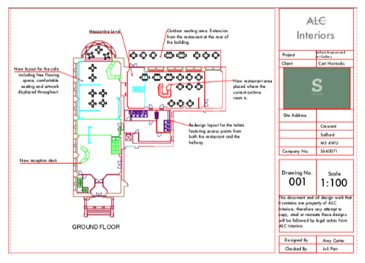
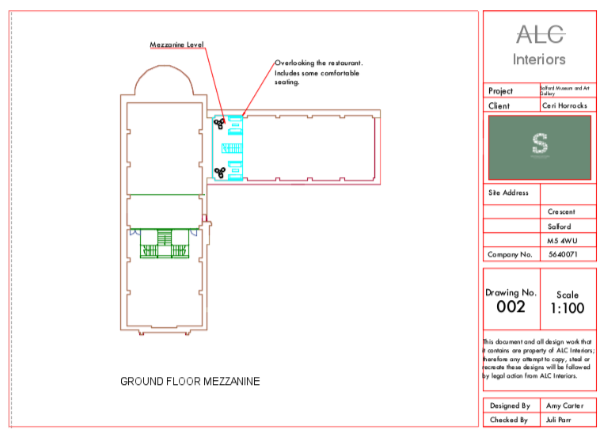
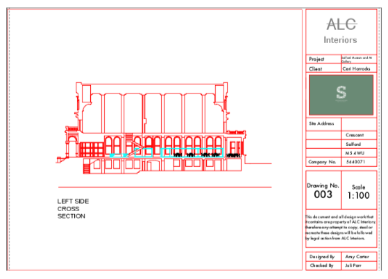
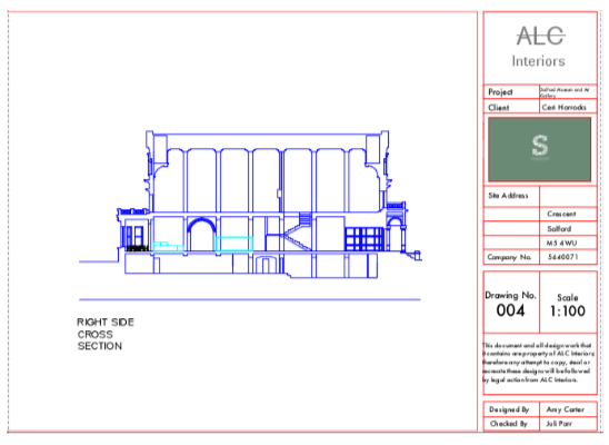
Throughout the first module: Advanced Studies in Interior Design I didn't particularly do much digital work for this project except the floor plans, elevations and construction drawing in AutoCAD. This is because I decided that I wanted to produce hand drawn visuals for this module instead of digital ones as this is going to probably be the last project I have the choice between the options and I do think their is something quite nice about hand drawn visuals. So throughout the last six weeks I haven't got much digital work to show but you can view my plans and elevations below.


Nov 4th, 2018
As I said all of my modules are going to be mainly digital based this year and after my first module the next two are my Advanced Research Strategies module and my Independent Research module which were both computer based but were both research projects instead of design projects. The first which I have been working on for a while is my Advanced Research Strategies module. I have been conducting research to inform and lead onto my Negotiated Major Project to make sure that the design proposal had been well researched and that the design I am proposing is feasible. The design I am proposing is to turn the site of Merchants Warehouse, in Castlefield, Manchester into a boutique hotel that's main focuses are on sustainability and wellbeing. To view my feasibility report click here.
For the second module which I have been focusing on for the last few months which is my Independent Research module(dissertation) I have focused on sustainable design and the environment as my dissertation had to link to my Negotiated Major Project. To view my dissertation click here.
Feb, 24th 2019
Throughout the entirety of this year I have also been working on my Applied Professional Practice module which is my year long project. One aspect of this which I have been working on both within my digital sessions throughout the year, as well as in my own time, which is this website which I have been working a lot on this year as I wanted to give my website a complete makeover and I must say I am now very happy with the outcome. Other than this website I have also been working on my digital, brand identity which includes my CV, logo, business card and manifesto. To view my CV click here.


April, 28th 2019
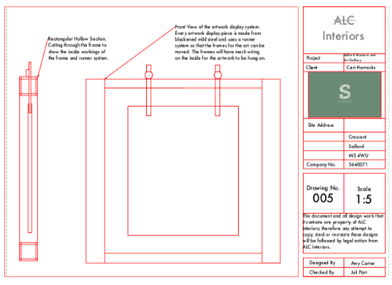
Finally, my last project, my Negotiated Major Project is the module I have the most to show for in terms of digital work and I have spent a lot of time both in my digital session and in my own time working tirelessly on this module as this is my biggest project I want it to be the best possible work I have produced. As I have already mentioned the site I am using for my Negotiated Major Project is Merchants Warehouse, in Castlefield, Manchester and I am redesigning it as a boutique hotel that focuses on sustainability and wellbeing. For this module a good chunk of the work has been computer based, which has included floor plans, elevations and sections; construction drawing; SkecthUp visuals; my Sketchbook; 'look and feel' board and my banner design which is to go on display alongside my work for my Degree Show.


May 2nd, 2019


Comments